Web Service Compositions: From XML Syntax to Service Models
Keywords: web services, xml, bpel4ws, model-based analysis, verification, validation
Abstract
This paper presents a rigorous approach to specifying, modelling, verifying and validating the behaviour of web service compositions with the goal of simplifying the task of designing coordinated distributed services and their interaction requirements. We address these issues through the use of rigorous software process analysis techniques, specifying semantics for web service composition standards and by providing an accessible, mechanical tool (as a plug-in to the Eclipse development environment), which automates the tasks involved. As web technology has evolved, an emphasis has been placed on providing ease of design for both visual content and functional services for users. Web Services however, concentrate on the view of systems inter-operating with other systems rather than that of actual human actors, yet the concepts for ease of design are highly related and desired. Firstly, this paper presents a model-based approach to the semantics of web service composition XML documents built upon formal verification, validation and simulation techniques, utilising scenario-based design and implementations built in service composition standards. Secondly, the work assigns the semantics of compositions through the use of Labelled Transition Systems (LTS) in the form of Finite State Processes (FSP). Thirdly, an environment is described forming a tool to assist in undertaking the approach.
Table of Contents
1. Introduction
Distributed Systems can yield a high level of complexity with difficulty in fully observing what the system can, cannot or will do in all states of execution. Recent inter-operability standards initiatives have aimed at reducing only the technical complexity, with the inherent issues of overall behaviour complexity still remaining. Web Service standards, such as the Business Process Execution Language for Web Services (BPEL4WS) [Curbera-et-al-2003] and the Web Service Choreography Description Language (WS-CDL) [Kaventzas-et-al-2004] are part of a group of initiatives that focus on addressing common inter-operability and interactions between services hosted on the internet. These standards however, do not consider appropriate engineering practices for designing complex interacting web services. Where previously designers of workflows had to work very closely with the developers of a technical solution, there is now a mechanism to support technology independent service composition and this provides opportunity for the designers to concentrate on exactly what is required from the composition without hindrance from limitations of technical possibilities or the effort required to implement such compositions.
Our work to date [Foster-et-al-2005] focuses on providing an approach and tool which facilitates the design of appropriate service interaction specifications, verifying implementations of these specifications and generating representations in the standards for web service orchestrations and choreography. We have achieved this through the provision of editors and views for analyzing the scenarios in service interactions and by verifying properties of the models produced through interaction specifications. This paper is organized as follows. In section 2 we describe a background to the analysis of web services and specifically how XML standards can be used to describe a web service’s behaviour. In section 3, we illustrate the approach to analyzing web service compositions described in XML standards. Section 4 details the translation of XML documents in BPEL4WS to the Finite State Process (FSP) notation used for modeling with Section 5 describing analysis through verification and validation of these models. Section 6 describes our tool support and Section 7 concludes the paper with opportunities highlighted as part of this on-going work.
The tool, described in this paper, is available for download at: http://www.doc.ic.ac.uk/ltsa.
2. Background
Whilst Web Services themselves are components with a clearly defined interface, the architecture lacks verification and validation of process behaviour in the composition and coordination of these services to the requirements and behaviour of users (or clients) of these services. This is in a similar way to that of analysing the impact of customisation and personalisation of web sites, in which the main problems associated with reusable compositions is that they are written without significant analysis of the potential use-cases and the needs of various clients [Bonnet2001]. We describe what constitutes a web service’s behaviour as;
“A web service’s behaviour is defined by the set of activities behind that service and mapping those activities to message exchanges.”
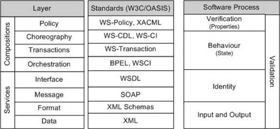
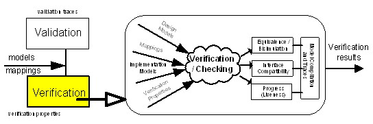
Web Service behaviour analysis consists of analysing two aspects of a web service architecture style. The web service formally exhibits its identity and permissible interactions through definition in the Web Service Description Language (WSDL) [Christensen-et-al-2001] . However, within the implementation for a web service the behaviour of its interactions is defined. The coordination of a service’s behaviour is formed from the basic operations of service invocation, replying to a service or receiving the reply from a service and this forms the basis for service analysis for its interaction behaviour. Standards elaborate the specification of how, what and when these interactions can occur. These XML standards can be aligned with that of software process analysis areas, as illustrated in Figure 1.
In essence, to analyse web services, we must consider what is defined by and behind the service interface, and consider those activities that comprise the process that the service offers. Web Service Behaviour Analysis can be described as;
“…..analysing the set of activities behind a service (a composition), and together with service interactions (choreography), provides an end-to-end view that models the role of each individual process in the choreography and the activities performed by each role.”
In this paper we concentrate on applying semantics to the process compositions defined in XML standards (which forms the behaviour and state aspects of a process) as implemented in BPEL4WS compliant documents. We now describe how this is formed in an approach which can be used within the composition development lifecycle.
3. An Approach to Analysing Service Models
Web service composition architectures aim to provide a technology independent means of integration, the ability to verify workflows is inherently not a technology issue but of state, behaviour and identity [Hruby1998]. A process has behaviour, persistent state which is not visible to the client and persistent identity which is visible through explicit user defined operations [OMG-CORBA2002]. Web service compositions (as processes) equally hold these characteristics. An approach therefore is required to provide steps to analyse each of these characteristics, but without limitations imposed from the underlying technologies involved. Process model verification can be used to identify parts of the process behaviour that have been implemented incorrectly, or perhaps have unforeseen property results. Whilst there have been other attempts to use model-checking techniques for reliable web service verification [Nakajima2002] [NarayananandMcllraith2002], they have concentrated on property specifications in domain specific language notations (e.g. Promela, the implementation language of SPIN).
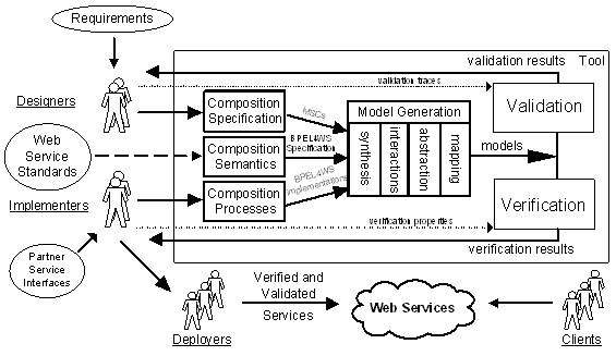
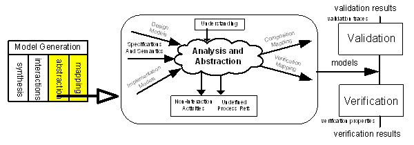
Our modeling approach takes the following steps to translate the activities specified in BPEL4WS documents to a neutral process algebra. We use the Finite State Process (FSP) notation to apply formal semantics to these activities. Given the BPEL4WS standard definitions and one or more BPEL4WS documents, we apply synthesis, abstraction and mapping to build models of the processes defined in these documents. The result of modeling is that a series of processes are defined in finite state machines, upon which formal analysis can be undertaken. An overview of this approach is illustrated in Figure 2.
Our verification approach utilizes an abstract functional design specification in the form of Message Sequence Charts (MSCs). The approach uses the UML style design of these sequences away from a technical implementation, and evaluates their transitional state and behaviour locally before deploying any parts of the workflow, and realizing the true effect of the process flow implemented [Uchitel-et-al-2001]. The verification side of the approach aims to provide a mechanism to support such questions as; can the implementation fulfil the interaction requirements and did we build the process interactions correctly?
4. From XML to Process Models
BPEL4WS is a standard in XML for specifying and executing service orchestration processes against a domain of web services. The ability to develop a standards based process execution notation emerged from earlier efforts of several competing specifications including the Web Service Flow Language (WSFL) [Leymann2001], XLANG [Thatte2001] and BPML [Arkin2002]. The desire is to form a standard way of coordinating a uniformed and collaborative mechanism to support multi-service interactions for a business or other process. This is seen as a critical element of making web services viable for wide spread use. The BPEL4WS standard is based on XML and is defined as being a layer above the WSDL. As we have discussed in previous sections of this paper, distributed systems integration requires more than the ability to conduct simple interactions by using standard protocols. The potential of Web Services as an integration platform will be better achieved when applications and business processes are able to integrate their complex interactions by using a standard process integration model. The interaction model that is directly supported by WSDL is essentially a stateless model of synchronous or uncorrelated asynchronous interactions. Models for business interactions typically assume sequences of peer-to-peer message exchanges, both synchronous and asynchronous, within state enabled, long-running interactions involving two or more parties.
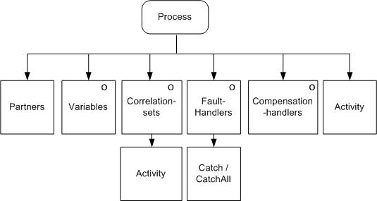
A basic process in BPEL4WS 1.1 is defined as a root element, consisting of one or more child elements describing partners, variables, correlationsets, faultHandlers, compensationHandlers and core process sub-activities (as illustrated in Figure 3).
A BPEL4WS document is split into five areas of process definitions. The first area of process elements covers process declarations. These do not directly influence the behaviour of the process, but are used to declare process wide declarations (such as partners, data containers used by the process etc). The declarations are used as reference in later stages of our modelling approach to associate interaction models between processes and its partners. The other areas of a BPEL4WS process specify the actual workflow of the process (e.g. interactions, conditional logic etc). Firstly, a set of constructs are used to specify basic interactions in the process (such as service invocation or receiving a request from a partnered service). We describe these activities as “primitive” in that they perform basic operations on behalf of the process. The second set of constructs defines the order in which activities are carried out. Such activities provide sequences of execution or concurrent activity execution. The remaining sets of activities are formed from the traditional programming language concepts (such as structured sequencing, iteration etc) and for specifying specific fault tolerance and compensation handling activities. We specifically group the conditional constructs of BPEL4WS, which we name “guarded process activities”, as they utilise a similar representation to that of guarded transitions. Guards define the flow of control in a computation, and how they may be translated under refinement is central to the formal treatment of models in model-checking techniques.
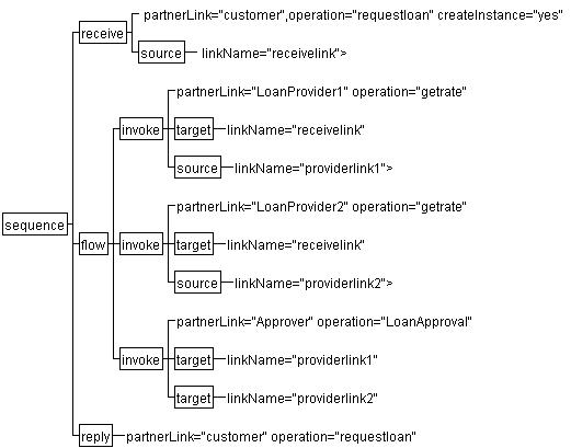
An abstract structure (XML tree) of a BPEL4WS document, for a Loan Approval process, is illustrated in Figure 4. Here, a sequence of activities is defined as a concurrent (flow) of three invocations (invoke) and a final activity of a reply back to the customer. The process is initiated by the request being received (receive) from a customer.
BPEL4WS Process Structure for Loan Approval Composition
A full list of BPEL4WS constructs is given in [Curbera-et-al-2003].
4.2. From BPEL XML to Finite State Machines
In theoretical computer science, a state transition system is an abstract machine used in the study of computation. The machine consists of a set of states and transitions between states. State transition systems differ from finite state automata in several ways: In a state transition system the set of transitions is not necessarily finite, or even countable. In a state transition system, transitions do not form a function, but a relation between the states, and therefore, there may be zero or more than one transition out of a given state, with the same input. State transition systems with a finite number of states and transitions can be represented as directed graphs. There are at least two basic types of state transition systems: “labelled” (or LTS for labelled transition system) or unlabelled. Although we could build representations in Labelled Transition Systems (LTS) directly, these representations work well with few states and that they become impractical to construct when defining larger LTSs. For this reason, Magee et al have proposed a simple process algebra notation called Finite State Processes (FSP) to textually specify LTSs. In addition, they have built the Labelled Transition System Analyser (LTSA) tool [MageeandKramer1999] that inputs FSP code to produce and analyse LTSs. FSP is a specification language with well-defined semantics in terms of LTSs, which provides a concise way of describing LTSs. Each FSP expression E can be mapped onto a finite LTS. FSP introduces several operators, including an action prefix, choice, recursion, an end state, sequential and parallel composition and equivalence minimisation. A summary of the semantics for FSP are listed below.
If x and y range over actions, and P and Q range over FSP processes, FSP introduces the following operators:
Action prefix “->”: (x->P) describes a process that initially engages in the action x and then behaves as described by the auxiliary process P.
Choice “|”: (x->P|y->Q) describes a process which initially engages in either x or y, and whose subsequent behaviour is described by auxiliary processes P or Q, respectively.
Recursion: the behaviour of a process may be defined in terms of itself, in order to express repetition.
End state “END”: describes a process that has terminated successfully and cannot perform any more actions.
Sequential composition “;”: (P;Q) where P is a process with an END state, describes a process that behaves as P and when it reaches the END state of P starts behaving as the auxiliary process Q.
Parallel composition “||”: (P||Q) describes the parallel composition of processes P and Q.
Trace equivalence minimisation “deterministic”: deterministic P describes the minimal trace equivalent process to P. If no terminating traces are proper prefixes of other traces, then it also preserves END states.
Strong semantic equivalence minimisation “minimal”: minimal P describes the minimal strong semantic equivalent process to P.
To analyse processes defined in XML, we firstly use the FSP notation to build a model of the semantics of a BPEL4WS process. The translation from BPEL4WS to FSP consists of a mapping between BPEL4WS schema specification semantics. A full guide to the translation is given in a separate paper [Foster2003] however; we illustrate this mapping with a sample set of constructs given in Table 1.
Sample BPEL4WS to FSP Translations
|
BPEL Construct Example and FSP Representation |
|
|
<sequence> <receive operation=”1” partner> </receive> <receive operation=”2” partner> </receive> </sequence> |
ACT1 = (receive_p1_p2_op1 -> END). ACT2 = (receive_p1_p2_op2 -> END). SEQUENCE = ACT1;ACT2;END. |
|
<switch name = "MPS"> <case condition= "cond1" = “true”> <receive…> <otherwise> <reply…> </switch> |
SWITCH = if cond1-true then ACT1;END else if cond2-true then ACT2;END else END. |
|
<while condition = “cond1” = “true”> <sequence> <receive…> </while> |
WHILE = If condition-true then ACT1;WHILE else END. |
|
<pick name =”pick1”> <onMessage> <invoke operation=”1” > <onAlarm> <invoke operation=”2”> </pick> |
PICK1 = ( event1 -> ACT1; END | event2 -> ACT2; END). |
|
<flow name=”flow1”> <receive operation=”1”>… <receive operation=”2”>… </flow> |
||FLOW1 = (ACT1 || ACT2). |
Whilst we represent different paths of a process with this method, we do not analyse the possible values of data messages (for example, if a switch/case statement is given, then each case statement is simply represented as an alternative path). An example translation using the semantics of BPEL4WS to FSP is given below.
// FSP Model Created by translation of BPEL4WS XML

// Loan Provider 1 interactions process
LOANAPPROVALPROCESS_INVOKELOANPROVIDER1 =
 (invoke_loanapprovalprocess_loanprovider1_getloanrate ->
 END).
LOANAPPROVALPROCESS_INVOKELOANPROVIDER1_REPLY =
 (reply_loanprovider1_loanapprovalprocess_getloanrate ->END).
LOANAPPROVALPROCESS_INVOKELOANPROVIDER1_SEQ =
 LOANAPPROVALPROCESS_INVOKELOANPROVIDER1;
 LOANAPPROVALPROCESS_INVOKELOANPROVIDER1_REPLY;
 END.

// Loan Provider 2 interactions process
LOANAPPROVALPROCESS_INVOKELOANPROVIDER2 =
(invoke_loanapprovalprocess_loanprovider2_getloanrate ->
 END).
LOANAPPROVALPROCESS_INVOKELOANPROVIDER2_REPLY =
 (reply_loanprovider2_loanapprovalprocess_getloanrate ->END).
LOANAPPROVALPROCESS_INVOKELOANPROVIDER2_SEQ =
 LOANAPPROVALPROCESS_INVOKELOANPROVIDER2;
 LOANAPPROVALPROCESS_INVOKELOANPROVIDER2_REPLY;
 END.

// Parallel composition process of FLOW interactions
||FLOW1 = (LOANAPPROVALPROCESS_INVOKELOANPROVIDER1_SEQ ||
 LOANAPPROVALPROCESS_INVOKELOANPROVIDER2_SEQ).
LOANAPPROVALPROCESS_INVOKEAPPROVER =
 (invoke_loanapprovalprocess_approver_approve ->
 END).
LOANAPPROVALPROCESS_INVOKEAPPROVER_REPLY =
 (reply_approver_loanapprovalprocess_approve ->END).
LOANAPPROVALPROCESS_INVOKEAPPROVER_SEQ =
LOANAPPROVALPROCESS_INVOKEAPPROVER;
LOANAPPROVALPROCESS_INVOKEAPPROVER_REPLY;
 END.

// Process for main sequence of BPEL4WS process
LOANAPPROVALPROCESS_SEQUENCE2 = FLOW1 ;
 LOANAPPROVALPROCESS_INVOKEAPPROVER_SEQ;
 END.
||CASE0 = (LOANAPPROVALPROCESS_SEQUENCE2).
LOANRISKSWITCH = CASE0RISKASSESSMENTRISKEVAL;
 END.
LOANAPPROVALPROCESS_REPLY =
(reply_customer_loanapprovalprocess_request ->
 END).
LOANAPPROVALPROCESS_SEQUENCE1 =
LOANAPPROVALPROCESS_RECEIVE1; LOANRISKSWITCH ;
LOANAPPROVALPROCESS_REPLY;
 END
+ {CASE0RISKASSESSMENTRISKOUTCOME_ALPHABET}.

// Architecture Models for BPEL Process
||LOANAPPROVALPROCESS_Instance =
(CASE0RISKASSESSMENTRISKOUTCOME
|| FLOW1 || LOANAPPROVALPROCESS_SEQUENCE1).
||LOANAPPROVALPROCESS_BPELModel =
(LOANAPPROVALPROCESS_SEQUENCE1).
4.3. FSP and Labelled Transition Systems
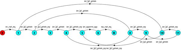
Compiling the full FSP translated from the BPEL4WS composition previously gives us a finite state machine, which can be represented graphically as an LTS, such as the example given in Figure 5.
5. Service Model Analysis
5.1. Analysis for the Service-Oriented Model
In the introduction to our work, we described verification of processes to be used to identify parts of the web service composition’s behaviour that have been implemented incorrectly, or perhaps have unforeseen interactions. This aims to satisfy such questions as; does the implementation match the requirements and was the process built correctly? Additionally, we can describe validation techniques in the approach as a mechanism to clarify the understanding of requirements against that of the implementation and that the result of validation is to ensure that the right process was built. The ability to perform verification and validation between implementations and design, and within the process compositions themselves, is a key requirement of the web services architecture specification (Booth, Haas et al. 2004).
To perform analysis and verification, we begin by applying an abstraction of the models built previously to yield refined models that do not include implementation specific details (such as resources, variable assignments etc). These models are then used in the analysis of interactions between processes and to trace these models to discover if properties are upheld or are violated.
5.2. Abstraction
Our approach to modeling in the tool, has at its core; synthesis, mapping and abstraction. We describe the model abstraction steps for web service compositions consisting of a series of tasks given input from the synthesis of initial design and implementation models and specifications and semantics of the processes modeled. The composition model elaboration is illustrated in Figure 6.
The process of abstraction is decomposed in to analysis of non-interaction activities in implementation (reduction), joining actions between design and implementation through specification semantics (grouping) and linking interactions between compositions through service interface models (mapping). The tasks of abstracting implementation specific activities, labelling appropriately in service interaction activities, hiding implementation specific activities and mapping between implementation and design composition models provides a typical set of characteristics in abstraction for model verification and validation [Gluch-et-al-2001] [Engels-et-al-2003]. Through our tool (discussed later), an MSC specification (also synthesized to FSP) can be included as a comparative design model with required interactions specified in an abstract form. To combine these models together requires us to map between activities in the BPEL4WS and in the MSC. To enable this, a mapping table is required to the BPEL4WS engineer to link activities in design and implementation. Here however, we focus on the abstraction for mapping interactions within and across web service composition processes.
The output of the abstraction steps are enhanced models including mapping information that can be used for joining composition process models, reducing the activities which are considered in the behavior analysis and verifying models of design against implementation models. The inputs to behaviour abstraction are the models from synthesis of a design and models from the translation of implementation discussed in the previous chapter. In addition to these models, the composition standards specifications and designer semantics are passed on through to assist in analysis of the elaboration techniques discussed later in this chapter. As highlighted previously, the composition standards are formed from the BPEL4WS specification - providing syntactic standards and suggesting semantics of how BPEL4WS processes are defined, implemented and formed and provide information on those activities which are candidates for reduction. The WSDL syntactic specification also provides semantics of service binding and linking with BPEL4WS partner interface extensions.
5.3. Synchronised Processes
A service conversation consists of a number of service partners and is considered in two ways. Firstly, the partner’s service has a process role in the choreography of the service scenario (e.g. to provide a book ordering service). Within that, or another service process, a partner of a service may be considered to have one or many roles depending on what behaviour the partner’s service provides. For example, a service partner in a BPEL4WS composition may labelled “Vendor”. This partner can be designated with one or many roles, such as in this case, both a “Seller” and a “Shipper”. The link to the partner and a list of their roles is defined by the client of the service composition. Therefore the service partner role semantics are defined locally to the process. The role indicator is used primarily to distinguish what the business process is referencing as part of the collaborative business service (for example, that the invocation from a buyer is in the context of conversation with another service acting as a seller).
To model interacting web service compositions there is clearly a need to elaborate our analysis of implementations by linking compositional interactions based upon:
activities within the process
identifying invocation style (rendezvous or request only)
identifying and recording the points at which interaction occurs
the abstract interface
linking between the private process activities and the public communication interface declared in the abstract WSDL service description
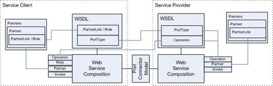
To model the semantics of linking interactions between processes requires a mapping between activities in each of the processes translated and building a message port connector for each of the interaction activities linking invoke (input) with receives, and replies (output) with the returned message to an invoke. In addition to the executable process of BPEL4WS, the specification’s abstract process defines PartnerLinkTypes, which are used as a class or type of relationship between a web service partner’s invocation and a corresponding receiving service partner port. These link types are then referenced in composition implementations to distinguish service interactions between two or more partners. For example, the linking and dependency of service partners, roles, service interface (WSDL) and the executable composition (BPEL4WS), along with where a modelling port connector is positioned is illustrated in Figure 7.
For every composition process selected for modelling we extract all the interaction activities in this process. As mentioned previously, interaction activities are service operation invocations (requests), receiving operation requests and replying to operation requests. In addition to an invocation request, we also add an invocation reply to synchronise the reply from a partner process with that of the requesting client process. The list is then analysed for invocation requests, and for each one found a partner/port lookup is undertaken to gather the actual partner that is specified in a partnerlink declaration. To achieve this, a partner list is used and the partner referenced in invocation request is linked back to a partnerlink reference. The partnerlink specifies the porttype to link operation and partner with an actual interface definition. To complete the partner match, all interface definitions used in composition analysis are searched and matched on porttype and operation of requesting client process. This concludes the partner match. A port connector bridge is then built to support either a simple request invocation (with no reply expected) or in “rendezvous” style, building both invoke/receive and reply/invokeoutput models. This supports the model mapping. The sequence is then repeated for all other invocations in the selected composition process, and then looped again for any other composition processes to analyse. We therefore specify an algorithm that will enable mechanical linking between activities, partners and process compositions.
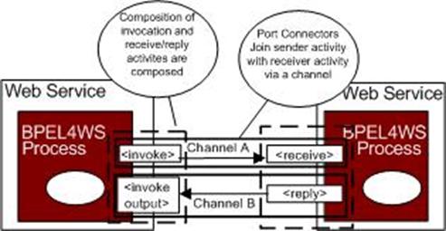
Our model of interactions using channels (illustrated in Figure 8) is based upon the composition state and not on the messaging architecture used for transport. In this way, we do not consider synchronous against asynchronous messaging models for modelling the communication flow between compositions. The model produced from analysis of the above is from the viewpoint of the composition performing as part of a role in choreography. This makes the model an abstract view of interactions for the purpose of linking invocations and not on the actual order of messages received by the process host architecture (synchronous and asynchronous messaging models for web services can be referred to in [Fu-et-al-2004].
The channels can be represented as models of these synchronized process interactions as illustrated in an LTS in Figures 9 and 10.
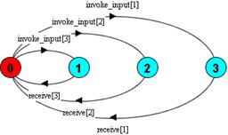
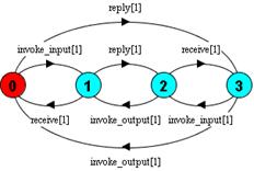
Combining the process models (described in section 4.) and port connector models illustrated here, provides us with a complete system model from which we can ask additional analysis questions – such as do the processes fulfill complete interaction cycles?
5.4. Verification
Verification is achieved through the use of formal software process model checking techniques, but we evaluate specific topics of our approach for web service compositions by wrapping and applying these techniques under the notions of deadlock freedom and safety and progress property analysis. Firstly, we can check the behaviour of a composition or choreography is deadlock free (i.e. that there no states with no outgoing transitions). In a finite state model a deadlock state is a state with no outgoing transitions in these models. A process in such a state can engage in no further actions. The deadlock states we are interested in are those that arise from a parallel composition of concurrent activities in a single composition, a number of interacting compositions and one or many compositions against that of their design specifications. This analysis can be performed simply by input of a series of processes and using a parallel composition to build an architecture model. A breadth-first search of the model is then performed and trace results can be obtained of the activities taken from the start state to the state at deadlock. An example of a deadlock state in web service choreography is that two services are waiting to receive a message from each other. The processes of these services are clearly in a deadlock situation where one is awaiting the other, and will never transition past this state.
Secondly, we can use safety property checking techniques to determine if given model properties are satisfied in one or many compositions. Safety properties are distinguishable from deadlock states in that they result in an error state – identified uniquely within a trace of the given model analysed. For example, if a safety property is composed with a given model, a safety check will result in error if the property is not preserved in the composed model. Safety properties used on complex systems are usually better stated as what is required, rather than stating what is not required. Thirdly, we can use progress properties (one of several liveness property analysis types) to assert that whatever state a system is in, it is always the case that a specified activity will eventually be executed. Progress is the opposite of starvation, the name given in a concurrent programming situation in which an action is never executed. Progress properties are simple to specify and are sufficiently powerful to capture a wide range of liveness problems in concurrent processes.
The process of using verification in analyzing the service models is illustrated in Figure 11.
5.5. Validation
For validation we provide additional mechanisms for designers to validate web service composition design specifications through simulation and animation. Assertions are used to identify properties for service interactions in a simulation of the composition, again from the model built in previous chapters. Animation is also provided, whereby designers are able to walkthrough scenarios of the composition, and selectively choose different paths of execution to check requirement scenarios are fulfilled in the given design or implementation. To perform direct process analysis we use model checking techniques (such as deadlock, safety and progress properties to specify the checks we wish to perform against process models. Whilst deadlock and safety can be performed generally (through direct instruction to an analyser) safety and progress can also be applied subject to those properties of interest or required by an end-user (for example, to directly assert whether a system can perform a series of activities or that the system exhibits to necessary behaviour to complete and fulfil a property). These more “end-user” properties are considered related to policy verification and validation. Preparation for property checking using such concepts is discussed in the next section of this chapter.
5.6. Results
Results of checks provide implementers and designers with useful details such as missing interaction cycles (e.g. a missing receive or reply action). Checks are undertaken by the main LTSA model-checking module. An output view summaries actions undertaken by the LTS compiler, and reports on property violations, such as deadlock, liveness or other safety properties. For example, to check compatibility of these compositions against loan assessor, provider and approver compositions the tool performs a safety analysis of the choreography model, analysing it for deadlock freedom. The result of such verification performed on the composition analysis can be illustrated back to approach users in the form of MSC, as illustrated in Figure 12.
Composition:
LOANAPPROVALPROCESS_Instance =
CASE0RISKASSESSMENTRISKOUTCOME.riskAssessment.risk:
LOANAPPROVALPROCESS_variable
|| FLOW1.LOANAPPROVALPROCESS_INVOKELOANPROVIDER1_SEQ
|| FLOW1.LOANAPPROVALPROCESS_INVOKELOANPROVIDER2_SEQ
|| LOANAPPROVALPROCESS_SEQUENCE1
State Space:
 2 * 3 * 3 * 14 = 2 ** 9
Analysing...
Depth 10 -- States: 14 Transitions: 17
Trace to DEADLOCK:
  receive_customer_loanapprovalprocess_request
  invoke_loanapprovalprocess_loanprovider1_quoterate1
  reply_loanprovider1_loanapprovalprocess_quoterate1
  invoke_loanapprovalprocess_loanprovider2_quoterate2
  reply_loanprovider2_loanapprovalprocess_quoterate2
  invoke_loanapprovalprocess_approver_loan_approval
Analysed in: 0ms
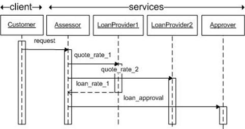
Figure 12. Violation as analyzer progress (above) and MSC (below) exhibited from a Compatibility Check on Loan Approval Choreography
The reason for this deadlock is suggested in the trace of invoke actions without a reply from the approver – in this case the engineer refers to the Approver composition and observes that there is no reply action specified. Using our tool, the engineer can perform this trace of interactions back to the Approver composition and amend the process to fulfil the reply and complete the conversation model. The process of verification, as with design and implementation is an iterative feature of the approach and as such repeated verification can assure the engineer that sufficient composition and choreography detail has been specified.
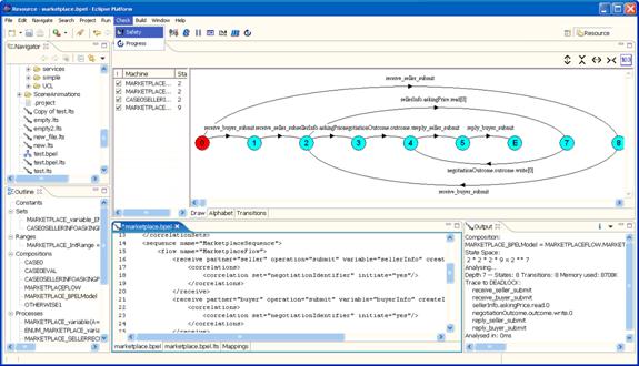
6. Tool Support As an Eclipse Plug-in
Tool support for this approach is provided as an extendable plug-in to the Eclipse Integrated Development Environment (IDE). Editors are included for MSCs, BPEL4WS and WS-CDL implementations. The tool required a composed set of modules to mechanically provide the steps necessary to implement the approach described in earlier chapters. These modules can be expressed individually with regards to the design and implementation, specifying model abstraction and mappings, and executing the verification and validation steps. It is only when they are brought together however, that they ideally assist in ease of iterative design and implementation process. The integrated tool [Foster-et-al-2005] which we call LTSA-WS is built upon the Labelled Transition System Analyser (LTSA) written by Jeff Magee in Java. The Eclipse tool is illustrated in Figure 13.
7. Conclusions and Future Work
In this paper we have described an approach to modeling web service compositions based upon their descriptions constructed in the XML standards of WSDL and BPEL4WS. We have discussed properties of these models, including deadlock and interaction synchronisation, which can be used to check models comply with expected results. In our approach we utilize MSCs for designing service interactions and provide a mechanism to support verification of BPEL4WS implementations against these design specifications. We wish to broaden the range of specifications to include WS-CDL (for service choreography standards) and other behaviour standards for the service-oriented architecture. We also wish to continue describing compositional behaviour by elaborating on the wider choreography aspects of partnered services. This includes considering fault, compensation and transactional integrity within and between distributed processes. We are also evaluating the use of core Eclipse graphical modeling plug-ins, such as the Eclipse Modeling Framework (EMF) that may replace the custom MSC classes we have developed and for translation between graphical and textual notations the Meta Object Facility (MOF).
Acknowledgements
- [Arkin2002]A. Arkin, Business Process Modeling Language (BPML), BPMI.org, 2002.
- [Bonnet2001]M. Bonnet, "Personalisation of Web Services: Opportunities and Challenges”, in Ariadne, June 2001.
- [Christensen-et-al-2001]E.Christensen, F.Curbera, G.Meredith and S.Weerawarana, " Web Services Description Language (WSDL) 1.1" W3C Note 15 March, Arbia, International Business Machines Corporation, Microsoft, 2001.
- [Curbera-et-al-2003]F. Curbera, Y. Goland, J. Klein, F. Leymann, D. Roller, S. Thatte, and S. Weerawarana, "Business Process Execution Language For Web Services, Version 1.1," 2003.
- [Engels-et-al-2003]G. Engels, J. M. Kuster, R. Heckel, and M. Lohmann, "Model-Based Verification and Validation of Properties," Electronic Notes in Theoretical Computer Science, vol. 82, 2003.
- [Foster-et-al-2003]H. Foster, S. Uchitel, J. Magee, and J. Kramer, "Model-based Verification of Web Service Compositions," presented at Eighteenth IEEE International Conference on Automated Software Engineering (ASE), Montreal, Canada, 2003.
- [Foster2003]H. Foster, "Mapping BPEL4WS to FSP", Technical Paper, Department of Computing, Imperial College London, London, UK,2003
- [Foster-et-al-2004]H. Foster, S. Uchitel, J. Magee, and J. Kramer, "Compatibility for Web Service Choreography," presented at 2nd IEEE International Conference on Web Services (ICWS), San Diego, CA, 2004.
- [Foster-et-al-2005]H. Foster, S. Uchitel, J. Magee, and J. Kramer, "Tool Support for Model-Based Engineering of Web Service Compositions," presented at 3rd IEEE International Conference on Web Services (ICWS2005), Orlando, FL, 2005
- [Fu-et-al-2004]X. Fu, T. Bultan, and J. Su, "Analysis of Interacting BPEL Web Services," presented at 2nd IEEE International Conference on Web Services (ICWS), San Diego, CA, 2004.
- [Gluch-et-al-2001]D. P. Gluch, S. Cormella-Dorda, J. Hudak, G. Lewis, and C. Weinstock, "Model-Based Verification: Abstraction Guidelines," Software Engineering Institute, Pitssburgh, PA (CMU/SEI-2001-TN-028), 2001.
- [Hruby1998]Hruby, P, “Specification of Workflow Management Systems with UML. OOPSLA Workshop on Implementation and Application of Object-oriented Workflow Management Systems”, Vancouver, BC, 1998.
- [Kaventzas-et-al-2004]N. Kavantzas, D. Burdett, G. Ritzinger, T. Fletcher, and Y. Lafon, "Web Services Choreography Description Language Version 1.0 - W3C Working Draft 17 December 2004," 2004.
- [Leymann2001]F. Leymann, "Web Services Flow Language (WSFL 1.0)," IBM Academy Of Technology 2001.
- [MageeandKramer1999]J. Magee and J. Kramer, Concurrency - State Models and Java Programs: John Wiley, 1999.
- [Nakajima2002]S. Nakajima, "Model-Checking Verification for Reliable Web Service," presented at OOPSLA 2002 Workshop on Object-Oriented Web Services, Seattle, Washington, 2002.
- [NarayananandMcllraith2002]S. Narayanan and S. A. Mcllraith, "Simulation, Verification and Automated Composition of Web Services," presented at Eleventh International World Wide Web Conference (WWW-11), Honolulu, Hawaii, 2002.
- [OMG-CORBA2002]"CORBA 3.0.2 specification," Object Management Group (OMG), OMG Technical Document Number 2002-12-02, 2002.
- [Thatte2001]S. Thatte, "XLANG - Web Services For Business Process Design," Microsoft Corporation 2001.
- [Uchitel-et-al-2001]S. Uchitel and J. Kramer, "A Workbench for Synthesising Behaviour Models from Scenarios," presented at the 23rd IEEE International Conference on Software Engineering (ICSE'01), Toronto, Canada, 2001.
Biography
Howard is a Research Assistant in the Distributed Software Engineering group at Imperial College London. He obtained his Bachelor and Masters Degree in Computer Science from the University of East Anglia and has recently submitted his thesis for Doctor of Philosophy in Computer Science at Imperial College. He also has over 10 years technical consulting experience in Distributed Technology and Internet Solutions.