Making the right constraints for usable and accessible user interfaces
Keywords: Application architecture, Conformance testing, Content Management, Content Model, Content Repurposing, CSS, Custom Publishing, Deployment, Enterprise Content Management, Graphic, Internet, RELAX NG, Repository, Stylesheet, XHTML, XML, XML Publishing, XSLT
Abstract
Many applications now use XML as a data exchange format and store data in some type of XML database system. Because of its wide applicability and the vast range of design patterns XML offers, developers are often overwhelmed when it comes to building applications. Many of the problems encountered centre around the multitude of variables and the difficulty in finding constraints to make them manageable. These are not inherent problems of XML itself but of constructing the right tools to enable the developer to find the right parameters for their application.
This paper focuses on managing constraints in a way that enables developers to create an accessible and usable user interface (UI). The constraining processes presented in this paper comprise of a language to describe a logical web page in an application, a basic bottom-up repository management system and the processing required for compiling pages. The design is intended to meet the following goals: i. Support for any XML input; ii. Support for XHTML and CSS output; iii. Support for page layout and graphic design constraints; iv. Support for W3C Web Content Accessibility Guidelines (WCAG) [http://www.w3.org/TR/WCAG10/] and US Government Accessibility Guidelines Section 508 [http://www.access-board.gov/sec508/guide/1194.22.htm]; v. Support for a wide range of applications;
The implementation of that design aims to provide a framework for customization of a user interface and support for rendering the user interface in multiple output formats (and on different devices).
The languages are defined using Relax NG and the processing is developed in XSLT 2.0. At a high-level the user interface is constrained to a logical page model which is easily understood by the user: Constraints identify a limited but complete set of loosely coupled UI components that can be pulled from a centralized UI repository and built bottom-up across a range of applications. We outline compiling of XSL, XHTML and CSS from this base repository and a framework that will support the output of additional formats. Also, we create a custom version of the XHTML schema to validate the quality of the output against our initial constraints. We outline a use case for this model, pushing out the User Interface for a large web application and show positive early results illustrating the efficiency and scalability of this approach.
Table of Contents
1. Introduction
While the interoperability and extensibility of XML enables new opportunities to connect technologies, it also offers an overwhelming range of new possibilities to create complicated applications. Facing the multitude of variables, parameters and possible combinations, developers might encounter difficulties in finding the right constraints to keep their applications manageable.
1. | How to choose the parameters for a specific User Interface (UI)? | |
2. | How can different visualizations be combined for use in a coordinated and uniform way? |
CSW has been developing a tool to address this very issue. This paper outlines the development of an automatic user interface generation tool. We propose an approach that breaks down the complex problem of user interface creation into a series of simpler problems, allowing the appropriate people to have control over the appropriate sub-tasks to make it easier to manage. Screen designs are dissected into components, and the processes that create the interface are broken down into a large pipeline. In particular this means that the UI itself can be designed by User Interface specialists, and application code can be written by Software Engineers, avoiding the almost inevitable problems that result when these roles become blurred.
We focus on the use of XML technologies and their role in our processes to be usable and useful. We outline some approaches, coordinating multiple visualizations of data using XML based technologies. Furthermore, we developed a tool to modularize and encourage re-use of existing components. We wanted end-users to be able to easily identify these segregated parts in the visual output for two reasons:
1. | We expect that in the future users will be able to adapt
an interface to their preferences, based on our component
modularization. | |
2. | We believe that functional design will result in very clean
modular interfaces. |
We wanted to facilitate making minor changes to UI's without having to create a complete new UI. Also, we wanted to develop a range of different visualizations for each interface to support different devices, as well as different user requirements. We wanted to create UI's that were usable, accessible and standards compliant, and we intended to use our experience with XML schema technologies to ensure the correctness and validity of every screen design.
NOTE: Code fragments in this paper have been simplified to express common cases rather than the full generality of some of the problems discussed.
2. The logical screen specifications
We defined a logical screen specification language in order to associate the UI components with activities relating to document presentation, rather than document (i.e. data) creation. People trained in usability and graphics were our main target for this specification language i.e. the designers and developers of the UI.
Having a standardized specification, provided these designers and developers with a mechanism to control the UI independently of the transformation of the data itself, the final document output formatting and the rendition. The role of a screen specification itself was to define a 'master guide' document or global template specification to control a range of variable and dynamic data visualizations in a coordinated and uniform way.
We developed a screen as a logical set of 'screen components', which will all be visible to the user. Each screen component contains a small, functional unit of screen display logic. The use of these components within a screen is coordinated in multiple displays via a common underlying specification, focused on direct manipulations of screen components.
There are two main types of components in our logical screen specification, i. components for blocking or grouping, and ii. components directly representing visual elements [Thissen1]. For the purpose of assembling and laying out the visual elements in a harmonious way, we established the rule that visual elements must be blocked and grouped (using 'block' and 'frame' elements). Visual screen components can be tiled or paneled together in these blocks, and this assembly can be guided by a layout grid if required, allowing the screen designer many ways to construct complex views from simple ones.
We can infer multiple output renditions or visualizations from these abstract blocks. Some renditions for more complex browser views may be guided by the underlying grid, other renditions may simply group and order components by position order. Future renditions may be even made more selective, concerning which types of components are displayed and in which order.
Although, technically creating a logical screen specification is similar to creating custom tag libraries in a server side language or using the Tiles Document Assembly Framework [http://struts.apache.org/userGuide/dev_tiles.html], conceptually it is very different, as the target users are screen designers rather than programming engineers. The functional parameters, that the screen designer needs to control, are generally entities you can see, touch or hear in the final output, which is usually distinctly different from acts and entities that may be controlled by programming logic. Arrangements of visual elements need to be easily distinguished by end-users and also easily controlled and manipulated in a document-centric fashion by screen designers. We minimized the number of fundamentally different kinds of components, that must be understood by the screen designer. Each visual component in the specification corresponds to a collection of components, stored in an underlying repository.
The idea is to allow the page designer to control anything required in the user interface, without being burdened with the complexities of programming and coding for multiple output vocabularies. We also aim to encourage screen designers to discover and re-use components that are pre-configured in a template repository, before considering whether to commission development of new components by the development team.
The specification sets up which component will translate each part of the input data, whilst laying out the components in presentation order, no control logic is defined in a specification (no components in the interface should be specified unless they can be perceived and can be manipulated).
Interfaces consist of collections of components, arranged in the specification document. The re-use of standard components, defined in a specification, leads to greater, and verifiable, consistency in the software interface. It also reduces the possibility of defects in design and implementation, leading to higher quality of the software product, and less effort (cost) in quality assurance.
The logical screen model illustrates the simple classification system used for specifying the semantics of a screen design.
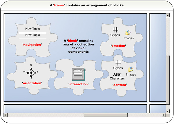
2.1. Frame and block elements
A page designer normally uses a grid when deciding on overall layout style and positioning of components (e.g. to position components to head or foot of the documents). The chunking and padding of visual components within a grid can improve alignment, visual hierarchy, balance, consistency, proximity and even contrast, while facilitating later insertions of input data in targeted locations.
2.2. Orientation elements
Orientation components help users find their way and detect where they are situated within an application. Commonly orientation components are an arrangement of pointers, marked in hypertext (e.g. site-maps, bread crumbs [http://www.webopedia.com/TERM/b/bread_crumbs.html], process staging diagrams etc.).
2.3. Navigation elements
These components help users move around a large multi-screened information space. Generally, these elements will provide the user with a navigation system, e.g. enabling the user to jump via hypertext links (such as links to main areas of information space, related links, useful links, help page links etc.).
2.4. Content elements
Content can be any information that resides on a computer and can be processed and displayed. Usually content is editorial or descriptive text, but it can also include many other types of information (images, illustrations, glyphs etc.).
2.5. Interaction elements
These are components that cause the computer to react to the users' activities. They include user inputs (such as dropdowns, checkboxes and textboxes), they may link to a range of terminology services or code lists and collect and send on the users' information for further processing and feedback (e.g. search box, interactive help, login etc.).
2.6. Emotion elements
These elements appeal to the users' feeling and are generally aesthetic rather than functional. They are used to encourage, invite or even motivate the user to work more efficiently with the system. How good something looks to us, its self-image and attractiveness can improve the usability (e.g. clip art, page furniture, call-outs, box-outs etc.).
2.7. Data navigation and XPath node pointers
Easily finding, filtering, partitioning, segmenting and selectively merging and combining subsets of data is very important. Raw information can originate from multiple documents and databases and may require additional aggregation, decomposition, merge operations and caching to be efficiently processed at runtime.
Information centered navigation and the aggregation of data within the specification was achieved by adding a 'match' attribute and other select attributes to all visual components. These functioned as an XPath [http://www.w3.org/TR/xpath] node pointer to processable units within input data. These XPath node pointers are passed onto components, allowing users to control the level of granularity at which data is processed and presented by a component.
<navigation name="list-hypertext-horizontal-tabs"
            match="/tocset/toc/tocset/toc">
    <select title="title" link="link/@uri" alt="title"/>
</navigation>
3. What makes a good screen component repository?
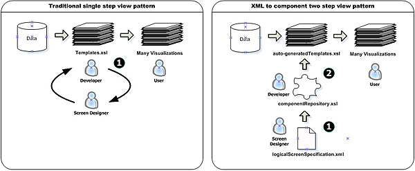
Clearly, screens and screen components are different things to different people and different systems. Our goal was to determine common structural denominators and to create a tool with broad applicability. The key concepts behind the repository we implemented, were a mapping between XML elements and software components, as well as a two-step view design pattern [Fowler1]. Also, an important operation in our implementation was the ability to move XML elements representing information into different visualizations and application interfaces, so they could be realized as different things to different people (different output forms, screens for different user levels, re-skinnable styles, user customizations etc.).
XML provided a very flexible way to define an abstract view or visual logic via a screen specification for the overall scheme, independent of its visualization. The example below is a simplified fragment of an XML screen specification, defining some layout, frames, blocks and a content component (see Example 1, “Screen Specification”).
Example 1. Screen Specification
<layout xmlns="http://www.csw.co.uk/layout">
  <frame  cols="10" rows="5">
    <block cols="2" rows="1">
      <content match="/article//listitem" templateid="listmanager"/>
    </block>
    <block/>
    <block/>
     ...
  </frame>
</layout>
This document-orientated XML is optimized for information-centred aggregation of input XML from various sources using XPath node pointers. Its hierarchical structure makes it easy to process with XSLT, resulting in simpler processing to multiple outputs from a range of components. Using a logical screen specification, we had all the information we needed to construct a visualization from a repository. This logical screen specification describes the configuration of a screen design in its simplest form, based on some constraints and access to a list of pre-configured components. Obviously, we needed a mechanism to associate the information to be conveyed to the user of the application with a collection of re-usable components in a repository. How might that be done?
We used XSLT 2.0 to transform element representations in the specification into output components. These auto-generated components could transform the XML input data to realize a range of different visualizations for different users. We used a two-step view design pattern in our processing pipeline to reorganize and simplify processing. The first view step in our pattern auto-generated style sheets from the XML component representation, defined in our specification. In a second step, we ran our style sheets against our input data within the application. The main advantages of using a two-step approach were the following: i. We could get more variations for less code because the two-step process - in contrast to a one-step process - leads to combinatorial explosion. ii. We could re-organize the processing, so almost all the manual checks required were done at the earliest possible stage and at the component level, making it possible to auto-check components rather than the infinite end-products. iii. Our deployed style sheets ran much faster than they would in a single step approach due to pre-processing and compilation.
1. | We could get more variations for less code because the
two-step process - in contrast to a one-step process – leads to
more rendition possibilities. | |
2. | We could re-organize the processing, so almost all the manual
checks required were done at the earliest possible stage and at the
component level, making it possible to auto-check components rather
than the many potential pathways in the UI of the end-products. | |
3. | Our deployed style sheets ran much faster than they would
in a single step approach due to pre-processing and compilation. |
Illustrated below in Example 2, “XSLT Processing” is a simplified XSLT processing (stylesheet-generating stylesheet), that could be used to auto-generate a screen, using components from a simple developers repository (stored in repository.xsl).
Example 2. XSLT Processing
<xsl:stylesheet version="2.0"
  xmlns:xsl="http://www.w3.org/1999/XSL/Transform"
  xmlns:oxsl="http://www.w3.org/1999/XSL/TransformAlias"
  xmlns:layout="http://www.csw.co.uk/layout">

  <xsl:namespace-alias stylesheet-prefix="oxsl" result-prefix="xsl"/>

  <xsl:template match="layout:layout">
    <oxsl:stylesheet version="1.0"
      xmlns:xsl="http://www.w3.org/1999/XSL/Transform"/>
      <oxsl:template match="/">
        <html><body><xsl:apply-templates/></body></html>
      </oxsl:template>
      <xsl:copy-of
        select="document('repository.xsl')/xsl:stylesheet/*"
        exclude-result-prefixes="oxsl layout"
        copy-namespaces="no"
        xpath-default-namespace="xsl"/>
    </oxsl:stylesheet>
  </xsl:template>

  <xsl:template match="layout:frame">
    <xsl:apply-templates/>
  </xsl:template>

  <xsl:template match="layout:block">
    <div><xsl:apply-templates/><div>
  </xsl:template>

  <xsl:template match="layout:content">
    <oxsl:call-template name="{@templateid}">
      <oxsl:with-param name="content" select="{@select}"/>
    </oxsl:call-template>
  </xsl:template>

</xsl:stylesheet>
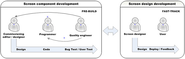
The development and test cycle diagram below illustrates the screen design process. To produce better quality interfaces more efficiently, we created an interface builder. The biggest benefits for screen designers in this system were in the 'fast-track' or 'rapid build' area, where we specified graphics by constructing screens from a repository collection of fully tested primitives and partial designs.
A high level of customization is essential to create very specific user interfaces with pre-existing component repositories. The extensibility of XML made it simple to add new customizations. Using schema technologies to register and maintain some constraints uniformly, is important to guarantee consistencies in the visualization of the interface. Examples of customization would be the coordination of interaction elements to process XFORMS [http://www.w3.org/MarkUp/Forms/], or the customization of content elements to process Docbook style sheets [http://docbook.sourceforge.net/projects/xsl/] or other third party tools (see Example 3, “”).
Customization SpecificationExample 3.
<layout xmlns="http://www.csw.co.uk/layout">
  <frame cols="10" rows="5">
    <block cols="2" rows="1">
      <content match="//article"
               stylesheet="/Stylesheets/docbook/xhtml/docbook.xsl"/>
    </block>
    <block/>
    <block/>
    ...
  </frame>
</layout>
In order to coordinate multiple output visualizations from our element representations, we used the new XSLT 2.0 multiple output document mechanism to create a forking mechanism in our pipeline. This generated a range of different visualizations from a single specification (see Example 4, “XSLT2 Specification”).
Example 4. XSLT2 Specification
<xsl:stylesheet version="2.0"
  xmlns:xsl="http://www.w3.org/1999/XSL/Transform"
  xmlns:oxsl="http://www.w3.org/1999/XSL/TransformAlias"
  xmlns:layout="http://www.csw.co.uk/layout">

  <xsl:namespace-alias stylesheet-prefix="oxsl" result-prefix="xsl"/>

  <xsl:template match="layout:layout">
    <xsl:result-document href="{layout:frame/@name}-xhtml.xsl" format="xhtml">
      <oxsl:stylesheet>
        <xsl:apply-templates mode="xhtml"/>
      </oxsl:stylesheet>
    </xsl:result-document>
    <xsl:result-document href="{layout:frame/@name}-xslfo.xsl" format="xml">
      <oxsl:stylesheet>
        <xsl:apply-templates mode="xslfo"/>
      </oxsl:stylesheet>
    </xsl:result-document>
    <xsl:result-document href="{layout:frame/@name}-text.xsl" format="text">
      <oxsl:stylesheet>
        <xsl:apply-templates mode="text"/>
      </oxsl:stylesheet>
    </xsl:result-document>
          ....
    </xsl:template>

</xsl:stylesheet>
XSLT 2.0 and XPath 2.0 also provided some powerful new features for mapping our specification blocks to a range of visualizations, such as HTML 'div's, HTML 'table's, Microsoft Word tables and many other table or divisional blocking semantics. Some useful new features included the counting in XPath, which we used to create a base grid. Also useful was the ability to recursively reprocess a variable. We used this to pour data, formed in blocks, into a base grid, one iteration at a time, while checking the integrity of the output rendition, using some of the new grouping features.
<xsl:variable name="output-numbered-html-grid-table-base-structure">
  <table>
    <xsl:for-each select="(1 to $y)">
      <xsl:variable name="row-count" select="position()"/>
      <tr>
        <xsl:for-each select="(1 to $x)">
          <td>
            <xsl:value-of select="($row-count * $x) -$x + position()"/>
          </td>
        </xsl:for-each>
      </tr>
    </xsl:for-each>
  </table>
</xsl:variable>
4. Developing a component for a screen repository
The development of components for a screen repository is a crucial step, as they will be represented by XML elements in a specification, re-used for different interfaces and moved individually or in groups among different visualization and application interfaces.
We made customization and development of new components easy and bottom-up. A high level of customization enables developers to freely organize components they create in any way that facilitated their documentation, registry and discovery from a common screen specification schema.
Equally important to registering a unique name for a component, is the registry of the various visualization modes that a component supports, e.g. a specification for an interface targeted at web browser, PDA and print would require access to a list of components that specifically support all modes of output. Documenting and registering components does involve more work for developers, but makes it easier for the screen designers, and the resulting interfaces are much more user-centered.
The components' role is to translate XML from XPath pointers to document-orientated XML, based on its logical screen specification. This often involved constructing visualizations from conditional, dynamic or static XML data. We avoided complex filtering and ordering by components. Data that needed complex sorting and ordering required custom pre-processing. We did this because it was important to distinguish the document presentation from the data creation, and, generally, it was more efficient to sort and order data with a query language, than by using tree manipulation.
In general, we found no benefits from complex inheritance and kept code simple, modular and componentized. This improved the speed of a final application and supported creativity, quality, and enjoyment for the end-users. Very simple designs often have a greater impact than more complex designs, because they are understood immediately. Additionally, uniformity was important because consistencies improve the usability of an interface.
Usually, we registered a new component by adding an additional 'name' attribute enumeration to a visual element representation in the specification. These new components comprised template rules in our repository, e.g. if we wanted to use the orientation component with the name "process-diagram", we would find a series of template rules matching it in several modes with a declarative rule 'match="layout:orientation[@name='process-diagram']"'. We also adapted a range of values, defined in the specification, to create several visualizations directly, e.g. for character definitions we used a XHTML [http://www.w3.org/TR/xhtml1/] naming system directly and re-used the names which had already been attributed in the specification (see Example 5, “Character Definitions”).
Example 5. Character Definitions
<xsl:template match="layout:characters" mode="xhtml">
  <xsl:choose>
    <xsl:when test="@name and @name!=''">
      <xsl:element name="{@name}">
        <xsl:apply-templates mode="xhtml" />
          <xsl:if test="@select and @select!=''">
            <oxsl:value-of select="{@select}/text()"/>
          </xsl:if>
        </xsl:element>
    </xsl:when>
    <xsl:otherwise>
      <xsl:apply-templates />
      <xsl:if test="@select!='' and @select!=''">
        <oxsl:apply-templates select="{@select}" mode="xhtml"/>
      </xsl:if>
    </xsl:otherwise>
  </xsl:choose>
</xsl:template>
There are two main parts to a component in a screen repository: the scheme and the style. Schemes and styles can be re-used independently across multiple components.
4.1. Scheme
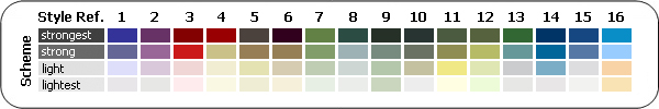
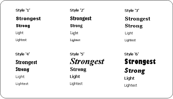
We define 'scheme' as the structure of a component. It determines the composition and the hierarchy of display within the component, e.g. we may define characters as being strongest, strong, light or lightest in the scheme, which is distinctly different from the style, that describes the font style, font weight, kerning, leading, etc.. The scheme relates more to its usability and accessibility than to its visual appearance.
In order to achieve a consistent look and feel in the output, we organized components to follow similar simple display hierarchies. For instance, almost all navigation and orientation in the XHTML [http://www.w3.org/TR/xhtml1/] renditions had the same scheme, which was an unordered list of hypertext links. Although semantically similarly structured, they were often styled very differently.
We also investigated producing different schemes for different user capability levels, such as beginning user, experienced user, inexperienced programmer and experienced programmer as defined by Ben Schneiderman[Shneiderman1]. We experimented parameterizing components to produce additional visualization renditions based on user level. So far, we didn't implement this yet, but are interested to develop this idea further in the future. The design, that is required to make an interface more usable for an experienced programmer, needed generally a much more elaborate scheme than that for a beginning user, and included access keys for links, more complex icon only toolbars, but much less information and help text, so the style was optimized for speed .
In general, we limited the number of levels of display hierarchy in components to approximately four levels to secure a high amount of interoperability and speed of intelligibility. Useful parameter values for hierarchy are the terms 'strongest', 'strong', 'light' and 'lightest' mentioned previously. These terms fit equally well, when working with the hierarchy of a color palette, the hierarchy in font usage (fontography), voice to speech. They even can be related to column layout and spacing of objects.
4.2. Style
We define 'style' as the appearance or voice of a rendition. Style changes generally accommodate preferences by identifiable groups of users and do not alter the meaning of the information being presented. We use scheme and style in combination, e.g. for a message 'pay attention', the scheme may be 'strongest' and style variations would include different kinds of dark heavy colors, big bold or prominent type faces, heavy borders, large spacing and definition etc.. Style controls manage the rendition of each object within each visualization, e.g. when outputting a XHTML [http://www.w3.org/TR/xhtml1/] visualization all style attributes were written in CSS, and when creating a XSL-FO [http://www.w3.org/TR/2001/REC-xsl-20011015/] almost all style controls were written out as attribute-sets.
To enable and enhance usability, accessibility and validation of the final output, it was important that style rules fitted a scheme. Style interoperability between components was improved by organizing most styles to a predefined scheme with schema constraints such as our 'strongest', 'strong,' 'light', 'lightest'.
Traditionally, different people applied style classes in different ways and this required standardization. In order to address this issue, we followed a set of rules for the context and the method of applying style classes or rules to improve interoperability and re-usability across different components. This gave us the ability to re-skin entire screens from grouped sets of style amendments. Additionally, it was easier and more precise to do automated checks later using schema technologies, since we had standardized contexts for styles on semantically identifiable units.
When working with color in components, various style palettes could be applied to alter the hue or saturation. We constrained the color to four relative color values with a pre-specified lightness. These constraints enabled us to set color schemes for color blind people at a component level and also removed the need for manual accessibility, checking for this condition on an infinite amount of output possibilities. Ultimately, we created a more usable interface by keeping the number of colors small, and by using relative values. This resulted in more consistency and clarity, which helped to form efficient mental models.
Similarly, a scheme of relative font sizes was styled. We implemented 'scalable' relative sizes where possible for our XHTML visualization for users with failing sight. An important consideration, writing the style part for components, was parameterizing and constraining values that could be customized in different visualizations.
We also started using Scalable Vector Graphics (SVG) [http://www.w3.org/TR/SVG/] to represent icons and other illustrations at a scheme level. We implemented this by dynamically generating images in different sizes and different formats for different visualizations, using the Batik rendering engine. We intend to investigate this further in the future.
We found many benefits from allowing customization of styles, and we hope to pass on these customizations to our users in the future - "a highly customizable application allows its user to 'teach' the application the manner in which the user wants to use it" [Tognazzini1] .
5. Bottom-up meets top-down
We developed components in a repository as a bottom-up process, while the process for specification of logical screens was top-down. The crucial question was, how to make these two apparently opposing approaches meet.
We used standard XML tools and schema technologies to make bottom-up meet top-down. Our logical screen specification was guided and constrained by direct associations to components, defined using schema technologies (Relax NG [http://www.relaxng.org/], W3C Schema [http://www.w3.org/XML/Schema] and Schematron [http://www.schematron.com/]).
By registering our bottom-up components in a schema for our top-down screen specification it was possible to create virtual foraging spaces, where components were presented in context and therefore easily accessible. The re-usability and speed of the system guaranteed a very low cost usage (unlike traditional component library development from a general archive, clip art or a framework library). These top-down processes for selecting and arranging graphical elements, using XML tools, were simplified by browsing and customizing from our bottom-up repository of previous use cases.
Particularly useful was the common functionality in many XML tools, facilitating guided use of values based on schema constraints. Many values in a logical screen specification represented components, and these specifications were modeled, defined, and guided by 'schema-aware' tools. Guided schema-aware tools gave us the possibility to browse and discover new components and alternatives within the top-down screen specification environment. Also, it minimized the amount of typing required through 'auto-completion' features. This was particularly useful when we already knew, which component we wanted to use and just needed to define it. Additionally, tools were helpful connecting a specification to a repository or build when no element data had been specified but was required. Here, the schema was read by the tool and default values were found, if required to build, from the repository. These techniques supported the designer in recognizing already existing solutions, including re-use.
We also used schema and Schematron validation to help users find and resolve problems with their screen definitions and intend to develop further help in the future, based around Schematron rules .
Previewing the interface for usability, accessibility and general verification early and often is crucial for rapid interface development and brings together top-down and bottom-up. We experimented with various methods for creating previews and are interested in developing these further to support information visualization and exploration. Improved visual aids will help screen designers connect better with the repository and component re-use. We had some successes in creating preview visualizations from test cases, using Sun's XML Instance Generator [http://www.sun.com/software/xml/developers/instancegenerator/], but have so far been unable to produce consistent results and high quality test cases from schema using this tool.
Another crucial factor connecting bottom-up and top-down was the availability of information exchange between them. Screen designers require up to date information on what components are available, otherwise they may re-commission development of new components. In order to achieve this, we had to automate a process to retrieve this information regularly. The automation and the retrieval of up to date component information was reliant on a uniform system of documentation and annotation, which we had used for each component.
We also developed a method of checking and guiding XPath pointers, which are used in our specification, based on variances of a schema for input data. This included some support for very simple XPaths, and we intend to develop this further in the future using Schematron and instance generation. Ultimately, we hope to implement these constraints at a later date.
6. Constraints and Validation
The choice of the right constraints is critical because they determine how information gets communicated, stored, formatted or delivered. The main purpose for developing constraints and validation in our system was to gather the semantics of the interface, to understand it, describe it and to improve it. Sometimes development resulted in relaxing constraints, and sometimes it resulted in adding new constraints.
Our constraint and validation processes were designed for a community of developers and screen designers, who are interested in improving the UI. The scope of constraints was limited to aspects that would improve usability and accessibility. It was also important to inform our users and match their expectations to what could be achieved within the constraints of the system.
We applied schema technologies to manage constraints. We used RELAX NG [http://www.relaxng.org/] as our primary schema language for all our user interface schemas. "RELAX NG is not simply well suited to describing vocabularies for which similar observations can be made, it is clearly superior to the other popular grammar-based schema languages: DTDs and W3C XML Schema" [Walsh1]. Our RELAX NG was usually validated using Jing [http://www.thaiopensource.com/relaxng/jing.html] and Sun's multi-schema validator (MSV) Schematron add-on [http://www.sun.com/software/xml/developers/multischema/] to carry out further checking against embedded Schematron rules.
Schematron [http://www.schematron.com/] provided a system to validate a set of additional constraints that couldn't be specified in RELAX NG or W3C Schema languages. Schematron constraints are rules-based and developed by specifying and declaring assertions about arbitrary patterns in XML (as we did with our UI XML). Using Schematron we could control and customize erroring from assertion failures and thereby provide useful informative guidance and help to developers and screen designers.
We also used W3C Schema in conjunction with RELAX NG because of the better tool support. Our W3C Schema was auto-generated using Trang [http://www.thaiopensource.com/relaxng/trang.html] . The W3C schema gave us the possibility to experiment creating a more graphical preview interface inside user environments, such as Microsoft Word in addition to other schema integrated XML IDE environments, such as XML Spy. Although free tools provide the functionality needed to create a guided specification such as Emacs with mode for editing XML files using RELAX NG [http://www.tei-c.org/Software/tei-emacs/] , we would like to develop a more user-friendly, easier to learn graphical environment in the future.
The constraints we implemented were focused mainly in two view areas: the logical screen specification for a broad band of communications (mostly prospective constraints [Piez1]) and the visualization of output from components for very specific message pathways (mostly retrospective constraints [Piez1]).
6.1. Prospective constraints
Our prospective constraints were the constraints on our logical screen specification used by a screen designer. These constraints identified the screen’s constituent parts as a preliminary step to further processing. The different elements of a logical screen were loosely coupled within blocks, representing more detailed component replacements in a following processing step. Our aim was, that these constraints would define the logical screen assembly pattern with no strong assumptions on how that would be rendered or visualized.
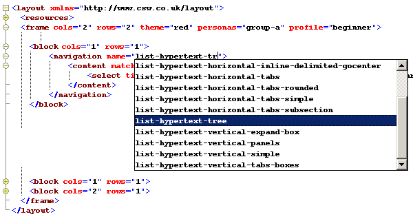
The schema brought together component representations, and we grouped them into a tiled model for visualization. We used schema technologies like RELAX NG and W3C Schema to constraint screen designers to our interoperable system of putting components in frames and block structures and not nesting blocks. Additionally, Schematron rules provided a method to check that the set-up of a group of blocks would tile together correctly within a grid controlled frame or layout.
Visual element components were more tightly restricted than grouping and blocking elements and were based on the registry of these components in the repository. Illustrated below is a RELAX NG compact schema fragment, listing the names of available components in the repository for navigation (the vertical bars indicate an "or" choice).
navigation.name.attrib = attribute name {
    "list-hypertext-horizontal-boxes" |
    "list-hypertext-horizontal-inline-delimited-breadcrumbs" |
    "list-hypertext-horizontal-inline-delimited-gocenter" |
    "list-hypertext-horizontal-tabs" |
    "list-hypertext-horizontal-tabs-rounded" |
    "list-hypertext-horizontal-tabs-simple" |
    "list-hypertext-horizontal-tabs-subsection" |
    "list-hypertext-tree"
    "list-hypertext-vertical-expand-box" |
    "list-hypertext-vertical-panels" |
    "list-hypertext-vertical-simple" |
    "list-hypertext-vertical-tabs-boxes" |
    }
We also permitted a high level of customization. Often the customization involved processing previously existing documents with previously existing XSLT. This was facilitated by adding a 'stylesheet' attribute, that allowed the option to process any XPath node pointer with any URL referring to a XSL style sheet.
<content match="//article"
               stylesheet="/Stylesheets/docbook/xhtml/docbook.xsl"/>
6.2. Retrospective constraints
Retrospective constraints were mostly used for quality assurance. They were applied at a component or screen level to our final output visualizations in order to check the quality of the message being output. Our retrospective constraints were mainly channel specific regarding message formatting, such as XHTML encoding, PDF, etc.. The constraints validated the syntax used for output formatting, the adherence to accessibility guidelines, the adherence to usability guidelines and information messaging (Has the information been transformed in the correct way? Was the correct type of data included? Did the data reach where it was required? Was it presented with clarity?). The goal was to standardize message delivery retrospectively in each channel, so that information could be processed accurately in adherence to many pre-defined rules and guidelines.
So far, we have focused mainly on constraining the XHTML visualization channel and intend to apply similar principles to other output visualizations, as our repository develops. We created a customization layer using James Clark's modularized XHTML schema [Clark1]. Our customizations allowed us to validate all CSS style classes used in our XHTML against specifically named sets, that had been pre-tested and approved. We also added many customized constraints to check for W3C Web Content Accessibility Guidelines 1.0 and US Government Accessibility Guidelines.
Traditionally, developers had used a range of tools to develop and test screens to pass quality and accessibility guidelines, and these processes required standardization. The tools included, i. W3C HTML and XHTML validation [http://validator.w3.org/] ii. W3C CSS validation [http://jigsaw.w3.org/css-validator/] iii. Watchfire Bobby (general quality and accessibility checking) [http://webxact.watchfire.com/ ] iv. WDG HTML Validator [http://www.htmlhelp.com/tools/validator/ ], v. CSE HTML Validator (Various HTML and CSS checks) [http://online.htmlvalidator.com/php/onlinevallite.php] vi. Doctor HTML (HTML checker with spell checking) [http://www2.imagiware.com/RxHTML/] and vi. Cynthia Says (Section 508 standards and/or the WCAG guidelines) [http://www.contentquality.com/]. We observed common errors affecting accessibility, such as missing 'alt' attributes on images, nested tables or tables without 'summary' attributes (e.g. as in embedded RELAX NG Schematron test below) and, one by one, began to add these checks to our own schema and Schematron rules. Schematron allowed us to run many additional rule-based checks, such as labels matching with input fields, interaction form inputs being correctly attributed with an appropriate action and submit button or internal links being referenced correctly.
s:assert [
          test = "@summary and @summary!=''"
          "table must have a summary attribute
           and text describing its contents"
         ]
We also checked that the Cascading Style Sheet (CSS) [http://www.w3.org/Style/CSS/] class names in the XHTML output were styles from an approved list and that they were applied in the correct context. We did this by registering each approved name as a valid option in an enumerated list, defined in our custom XHTML schema (see example below).
ul.attlist = attribute class {
    "list-hypertext-horizontal-boxes" |
    "list-hypertext-horizontal-inline-delimited-breadcrumbs" |
    "list-hypertext-horizontal-inline-delimited-gocenter" |
    "list-hypertext-horizontal-tabs" |
    "list-hypertext-horizontal-tabs-rounded" |
    "list-hypertext-horizontal-tabs-simple" |
    "list-hypertext-horizontal-tabs-subsection" |
    "list-hypertext-tree"
    "list-hypertext-vertical-expand-box" |
    "list-hypertext-vertical-panels" |
    "list-hypertext-vertical-simple" |
    "list-hypertext-vertical-tabs-boxes" |
    }
Generally, retrospective constraints facilitated error checking and iterative refinement of components during development. This led to the re-use of heavily tested and quality assured components and rapid interface development.
7. Project delivery
Our XML pipeline controlled orchestration towards implementation and ultimately project delivery. The pipeline processing model illustrates the processes we used to create logic screen specification, validate our specification, generate templates, preview the design, transform for output and validate the output. We used Apache Ant [http://ant.apache.org/] to manage most of the pipeline processing and all of the compilation and pre-processing of our application code. We chose this system as we were already using Apache Ant to compile Java source code.
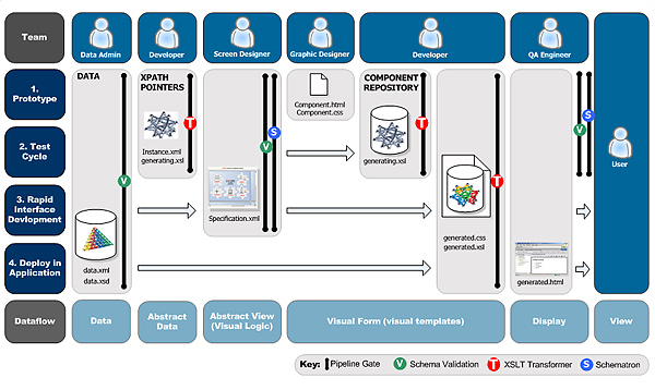
Our pipeline made it possible to deliver complex processing templates from a simple chain of reusable components. The logical screen specification optimized delivery by connecting only those components, that were required for the screen visualization and filtered out unnecessary processing early in the process. The logical screen specification also provided a single integrated work environment for delivering a range of visualizations and acted as a hub. This hub was processed with XSLT 2.0 for multiple output 'forking' for each visualization.
Two steps of viewing and validation made delivery more efficient: Allowing appropriate users to have control over the appropriate sub-tasks and allowing us the ability to check and validate at the earliest stage possible.
The ability to apply operations indirectly to graphical objects, representing information at the logical screen stage rather than fully visualized output, made processing more efficient. This resulted in a much quicker delivery, than what could have been achieved with complex traditional import and export procedures.
7.1. Prototype
Our prototyping involved that all team members manually developed processes, which could generate a UI, based on specific requirements for an application.
Test data was made available by a data administrator. The screen specification was constrained by a developer to only include data from valid sources. In a following step the screen specification was created by a screen designer, who negotiated with the developers and graphic designers downstream requirements and resulting needs for specifications. The developer then amended the set of stylesheet-generating stylesheets appropriately, transforming the specification document into the designs defined by a designer for each output visualization.
At the end of the prototype stage we had integrated the visual appearance of each component in each visualization. After we had established the visual design, the graphic designer in the team became redundant, and we moved on to a cycle of functional testing.
7.2. Test Cycle
During the test cycle we tested functionality of our application. This involved checking that each component was built correctly from the specification and that each handled the input data correctly in all visualizations. We also validated the final output visualization against a XHTML schema, customized to constrain the output into a more user-friendly and accessible subset.
At the end of this cycle, we tested that all the components could be built correctly in a range of visualizations and the developer was thereby redundant.
7.3. Rapid Interface Development
During the rapid interface development stage we finalized all screen designs. Having already established the set of required components and tested each component, the screen designer could work directly with users on the overall composition. The screen designer could re-organize and create new screen designs in many different ways, based on the collection of fully tested primitives and partial designs. These new and amended designs were then auto-generated and realized immediately, without the burden of creating further work for designers and developers downstream.
7.4. Deploy in application
The deployment stage involved taking the finalized auto-generated code from the finalized specifications and implementing these templates in the application. The deployed code had been optimized during pre-processing, so it only included the templates required for each visualization (an improvement on some traditional templating, which included complicated inheritance and inclusions of some unnecessary processing templates due to re-use).
8. Supporting change
Most system level changes occur in the domains of customization, quality enhancements and versioning, therefore our tooling had to be flexible enough to support these changes. We have found that iterative design and refactoring processes in our toolkit were most effective for developing user interfaces.
We used the Concurrent Versions System (CVS) for versioning and control. As a large amount of code was auto-generated by an Apache Ant build process from a component repository, it was crucial that auto-generated files were not manually edited at any point because this would have created maintenance difficulties.
9. Experimental evaluation
All the architecture presented has been implemented in XSLT using Ant and Java for control of pipelining and processing. In this section we outline some results from our first experimental evaluation of our approach and implementation.
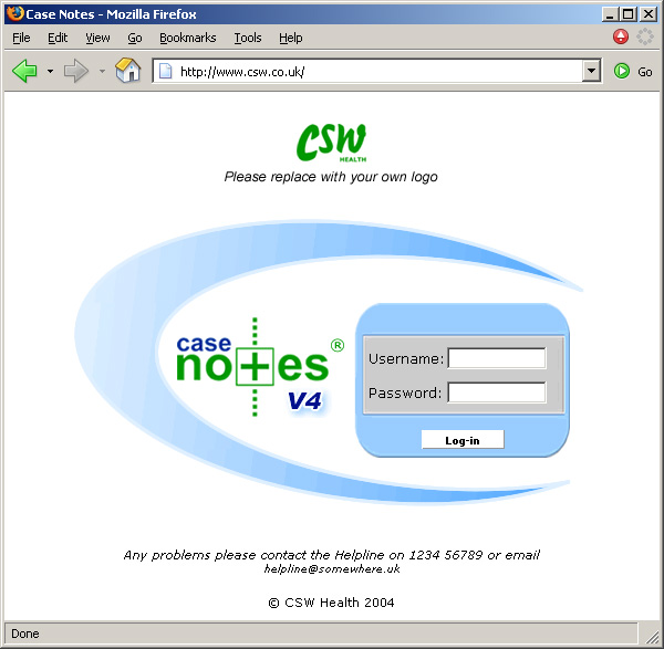
Part of the research involved prototyping screens in CSW's Case Notes Product.
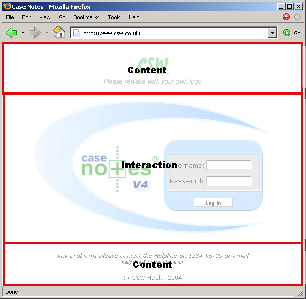
Visualization of the Case Notes Login interface was achieved through XML to component association.
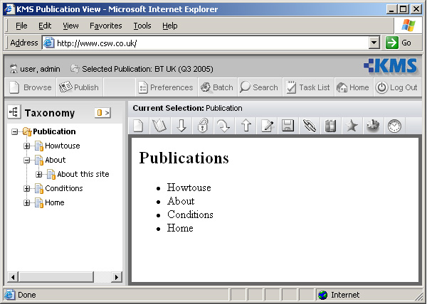
Part of the research also involved prototyping screens for CSW's Knowledge Management System (KMS).
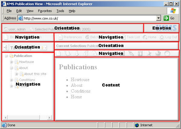
The Knowledge Management System (KMS) Interface
We found the screen specification useful for rapid development of a user interface. Screen designers apparently got better results from the system, when they had rough sketches or storyboard outlines ready beforehand. Although our constraints were helpful to guide users, we found that constraints could also force users to add more design details than beneficial at this early stage.
All XHTML interfaces were generated by using our pre-tested component architecture and repository and conformed to the standards when running the automated checks for accessibility and usability, that we outlined in previous sub-section 'Retrospective constraints'. In contrast, a traditional non-component approach requires several cycles of iterative development and testing to fulfill these standards.
Using the screen specification it was possible to make a presentation change in a single location that would effect multiple visualizations. Traditionally, this was not possible as a developer was required to make a series of edits to many different templates in each visualization.
10. Discussion and Conclusions
In this paper, we discussed the use of a logical screen and a component-based two step view design pattern [Fowler1] for creating interfaces in a range of visualizations. Components, represented by XML elements, provided a descriptive environment to associate XML data, aggregated in a specification with its visualizations. By using a component-based repository we achieved a high degree of extensibility and reusability.
Our system was designed for an environment, where multiple people were involved producing screens, and the use of XML and standards was critical for interoperability. Converting from a single step rendition process to the current two step rendition process was straightforward, and the benefits were obvious and immediate in our environment. In particular, we experienced significant quality improvements and time savings. Using our two step rendition allowed us to facilitate the processing for the screen designers at the cost of more complexity for the developers. People trained in usability and graphics were our main target, and addressing them gave good results.
Generally, there is an infinite number of ways to create a screen and therefore validation of quality, usability and accessibility is difficult. By using components, this infinite number is reduced to a more manageable framework and validation is facilitated. In the traditional single step process manual checking is proportional to the multitude of ways a screen can be formed. With a two step pattern, there are still many manual checkpoints involved, but reorganization and re-use of already checked components significantly reduced the amount of checks required. Quality improvements resulted from organizing these manual checkpoints at the component level and at the earliest possible stage.
Time is the main limiting factor when creating screen designs. The possibility for rapid interface development enables screen designers to instantly generate valid pages from a specification, or to make changes as required without needing new checkpoints, or affecting others working downstream.
The logical page specification empowers the screen designer to create complex and novel arrangements of components at the right granularity with no fixed assumptions on how and where the interface will be rendered. This would traditionally require extensive knowledge of numerous specialized interfaces, page descriptions and screen description languages. Deployment becomes simple and automatic.
Using a screen specification and XSLT to generate style sheets provides an inexpensive, efficient and customizable alternative to purchasing a commercial style sheet creation tool.
11. Future work and future directions
Our basic screen specification was targeted for a broad band of communications to end-users. However, it is clear that different specifications or views of a specification are needed for different people. One way we could accommodate this need in the future is by developing multiple levels of schema constraints, which could be applied to a logical screen specification. By applying these different levels we could for instance create a set of more relaxed constraints for creating sketches and story boards, a moderate level of constraints for screen designs and a high level of constraints for developers, who are used to working with precise information requirements. The processes outlined could also be redeveloped around a different type of specification and components for a different delivery mechanism. These different specifications could share common schema fragments, as in the levels mentioned previously, and become part of a larger repository network within a large system.
We intend to investigate additional uses for the specification. Ultimately, we could adapt it into a single integrated work environment for delivering a wider range of visualizations, rather than it being just a user interface specification. We could use the specification for interchange, such as drag and drop, across different frame visualizations, and support a wider range of visualizations within each rendition (e.g. such as allowing end-users to control how the data list will be displayed, such as in a table, chart, map or another visualization possibility for their data) [Prefuse1]. We are also interested in how to transform graphical interfaces into auditory interfaces for blind users to improve accessibility.
At present, there is still a lot that could be done to improve the current system. Following user-centered design practices, working with more users and solving remaining problems will be an invaluable experience for developing the tool in the future.
Additionally, we are trying to incorporate new technologies and better standardization. We want to introduce a more standardized approach to XML pipelining and use Document Schema Definition Languages (DSDL) to orchestrate how to apply a range of schema technologies to our interfaces. Also, we are interested in using micro-formats to create a more graphical environment in a web browser to define a specification. Finally, the development of CSS3 and XSL-FO will help us develop better renditions for our most commonly used visualizations.
Acknowledgements
- [Clark1]Modularization of XHTML in RELAX NGThai Open Source, June 1997. Available at http://www.thaiopensource.com/relaxng/xhtml/.
- [Fowler1]Two Step View, Martin Fowler, Part of EAA Catalog - Available at: http://martinfowler.com/eaaCatalog/twoStepView.html
- [Piez1]Beyond the 'descriptive vs. procedural' distinction, Wendell Piez, August 2001, Extreme Markup Languages 2001 ,Montréal, http://www.mulberrytech.com/Extreme/Proceedings/html/2001/Piez01/EML2001Piez01.html
- [Prefuse1]Prefuse: a toolkit for interactive information visualization, Jeffrey Heer, Stuart K. Card, James A. Landay Group for User Interface Research (GUIR), University of California at Berkeley, Available at http://guir.berkeley.edu/pubs/chi2005/prefuse.pdf.
- [Raymond1]Interaction Design System Use of XML, Michelle Raymond XML2001 - Available at: http://www.idealliance.org/papers/xml2001papers/tm/WEB/05-02-02/idsPaper.htm
- [Shneiderman1]Designing the User Interface: Strategies for effective human-computer interaction. Ben Shneiderman, Addison-Wesley Publishing Company, Reading, Massachusetts, second edition, 1992.
- [Tennison1]Managing Complex Document Generation through Pipelining, Jeni Tennison XTech 2005 - Available at: http://idealliance.org/proceedings/xtech05/papers/04-03-01/
- [Thissen1]Screen Design Manual: Communicating Effectively Through Multimedia. Frank Thissen, J.Rager, Springer, October 10,2003.
- [Tognazzini1]Tog on Interface, Bruce Tognazzini, Addison-Wesley, 1992.
- [UIML]OASIS User Interface Markup Language OASIS User Interface Markup Language (UIML) TC http://xml.coverpages.org/ms-xaml.html
- [Walsh1]Extreme DocBook Norman Walsh, Extreme Markup Languages Proceedings , 2004http://www.mulberrytech.com/Extreme/Proceedings/html/2004/Walsh01/EML2004Walsh01.html.
- [XAML]Microsoft Extensible Application Markup Language XAML (Extensible Application Markup Language) is a code-name for the Microsoft 'Longhorn' Markup Language. http://xml.coverpages.org/ms-xaml.html
- [XUL]The XML User Interface Language (XUL) Mozilla License - Available at: http://www.xulplanet.com/
Biography
Gary Cornelius began working in the publishing industry in 1992, following some early success as a student managing the production of a youth paper for the European Parliament. In 1993-1995 he completed an industrial apprenticeship based around digital imaging, where he experienced a wide range of positive changes brought about by computerization. In 1996-1999 he worked in Information Technology (IT) on a number of large scale consumer publishing projects, automating high quality PDF output from large databases and image repositories for Trader Media Group and various TV listings publications. In 2000-2003 he worked in software development as a programmer at Future Publishing Plc in their Internet Services research department on a project to unify publishing processes using XML. Since early 2004 he has worked for CSW Group Ltd. as technical consultant in the research department, specializing in XML, providing hands-on XML training at a series of XML Summer schools and training events in the UK. He also is an active member of Oasis and participates in several standards committees.
Dr. John Chelsom is Managing Director of the CSW Group, a company dedicated to providing information creation, management and delivery solutions using XML, Internet and database technology. Originally trained as an electrical engineer, John worked first as an X-Ray engineer and later gained a PhD for work on the application of knowledge based systems in medicine. Since founding CSW he has been responsible for the design and development of XML and SGML information management systems for some of the world's most prestigious engineering, healthcare and publishing organisations. John is a regular speaker at XML conferences, was a contributing author for the original SGML Buyer's Guide and is the presenter of the Technology Appraisals XML Seminar Series.